36+ process control system block diagram
Features such as dynamic torque boost or slip compensation control are typically offered to improve performance. In the temperature control loop example if the control system held the process fluid at 1005 C consistently even though the setpoint is 100 C then an offset of 05 C exists.
2
A block diagram of a.

. The NIOSH Engineering Controls Database has examples of published engineering control research findings. VANOS Solenoid Valve 2 - intake VANOS Solenoid Valve 2 - exhaust Crankshaft Sensor Blow-Off Valve 1 2 Hot-Film Air Mass Meter 1 2. LOAD DISTURBANCE A load disturbance is an undesired change in one of the factors that can affect the process variable.
A list of the equipment numbers along with a brief descriptive name for the equipment is printed along the top of the diagram. The definition of a closed-loop control system according to the British Standard Institution is a control system possessing monitoring feedback the deviation signal formed as a result of this feedback being used to control the action of a final control element in such a way as to tend to reduce the deviation to zero. The entire system is shown in the block diagram in the Fig.
Remove or block the hazard at the source before it comes into contact with the worker. One drawback of using VFDs is that it can get expensive and difficult to size. 8212017 Hareesha N G Dept of Aero Engg DSCE Blore 30.
Are part of the original equipment design. 22 Block Diagram of a Temperature Control System using LM35 27. 2014 E-Z-Go Industrial 875 48V Utility Vehicle Service Parts Manual.
10l0l Cdi Ignitor For Ezgo Golf Cart 4 Cycle Gas 1996 Pre Mci Robins Engine Replace Oem 72562 G01 Epigc107. The easiest way to wire a solenoid on a 36-volt EZGO golf cart is to follow the solenoid wiring diagram for the cart. To control tissue samples this process would be repeated separately for the control and disease.
You may know that PBCH output is 960 complex symbols long and that is divided into 4 parts and each parts are transmitted in consecutive System frames which can also. Figure 13 shows that each major piece of process equipment is identified by a number on the diagram. Payroll Management System 1519BEIT30052 36 Chapter 7 Component Diagram A component diagram describes the organization and wiring of the physical components in a system.
On 2006 Yamaha G22e Golf Cart Wiring Diagram. Heres a block diagram for control logic of the FRENIC Mini C2 VFD from the manual. A physical wiring diagram for the human immune system.
Process Systems Analysis and Control Third Edition retains the clarity of presentation for which this book is well known. The easiest way to wire a solenoid. The most effective engineering controls.
Drivers Door Switch Block Drivers Side Outside Mirror Passengers Side Outside Mirror. These packages allow the easy construction of block diagrams and quick analysis of control concepts to enable the student to explore Òwhat-ifÓ type problems that would be much more difcult and time consuming by hand. They could be described by the continuous-time mathematical equations todays controllers are predominantly digital systems so the block diagram of such a closed-loop control system can be represented rather by Figure 2Two new components are the DA and AD converters.
12 Flowchart of Project Methodology 15. 11 Diagram showing the process of Homeostasis 10. The location of these equipment numbers and names roughly corresponds to the horizontal location of the corresponding piece of.
Prevent users from modifying or interfering with the control. That we characterized here 171836. While the controlled systems are predominantly analog systems ie.
Manual Speed Control System A locomotive operator driving a train is a good example of a manual speed control system. The objective is to maintain the speed equal to the speed limits set. As you see from the above diagram a new MIB is generated by higher layers whenever the System frame number satisfies the condition System Frame Number Modulo 4 is zero SFN40.
Dynamic Stability Control DSC 41. Notice its complexity just with the sheer number of components. Component diagrams are often drawn to help model implementation details and double- check that every aspect of the systems required functions is covered by planned development.
2
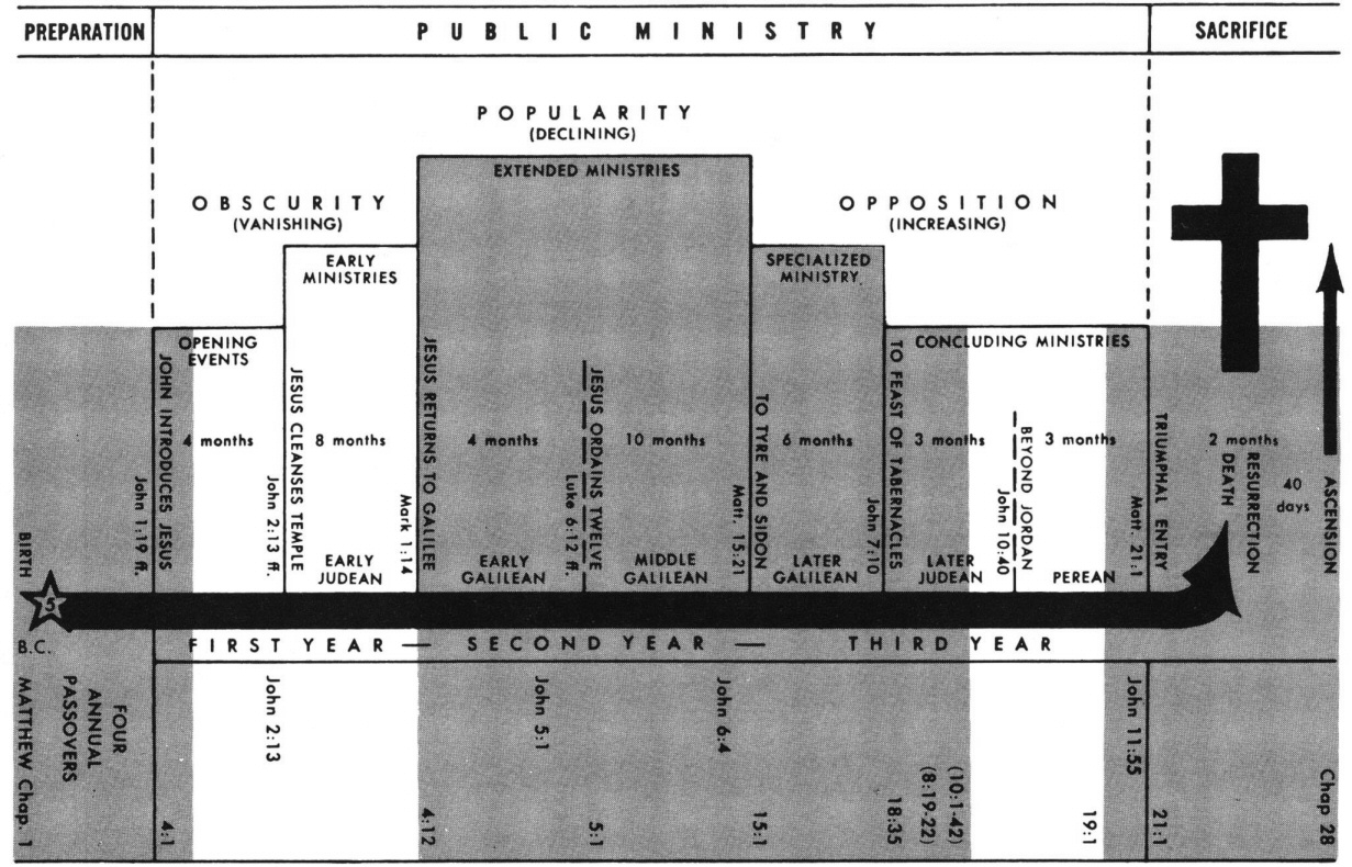
Matthew 13 Commentary Precept Austin

Development Of Fast And Hybrid Charger For Lithium Ion Batteries In Light Weight Electric Vehicles Sabarimuthu 2021 International Transactions On Electrical Energy Systems Wiley Online Library
Energies September 2018 Browse Articles
2

Presentation Materials
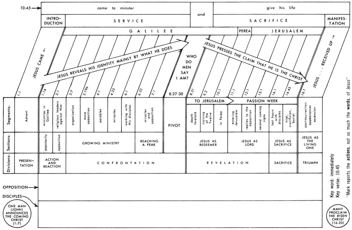
Mark 13 Commentary Precept Austin
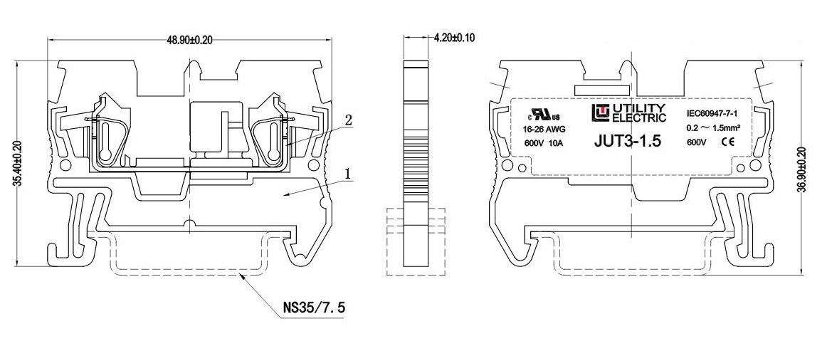
Din Rail Connectors Terminal Blocks Micros

Clinical Management Flow Diagram Download Scientific Diagram
Which Tissue In The Human Body Couldn T Run Exclusively On Ketones I Read That Ketones Can Cover Up To 50 Energy Needs Of The Body 70 Of The Brain The Rest Requires

Writing System Graphic Score Graphic Graphic Design Typography
367 Questions With Answers In Materials Studio Science Topic

Molecular Cavity For Catalysis And Formation Of Metal Nanoparticles For Use In Catalysis Chemical Reviews
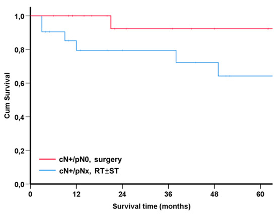
Diagnostics Free Full Text Frequency And Consequences Of Cervical Lymph Node Overstaging In Head And Neck Carcinoma Html
Luke 4 Commentary Precept Austin
Harvesting 62 Zn From An Aqueous Cocktail At The Nscl New Journal Of Chemistry Rsc Publishing Doi 10 1039 D0nj04411c

Femtosecond Laser Pulse An Overview Sciencedirect Topics